|
About Delgear is a computer software package for the integrated design and manufacture of generalized gear pairs. Such gear pairs include cylindrical, bevel, skew-axis, worm and worm wheel, along with non-circular gear pairs. This software is based on mathematical relations that differ from established standards and practice. This approach enables the following features: • Any face width • Any gear ratio (linear & nonlinear) • Any number of teeth • Any shaft angle • Any spiral angle • Any shaft center distance • Any tooth profile. These mathematical relations seamlessly encompass different gear types to design and manufacture gear pairs. A GUI is presented using a single nomenclature and software package.
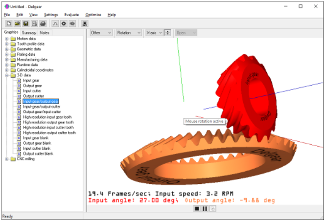
Main dialog window The software package Delgear is controlled with the above main dialog window. Three tabs comprise the left pane of the split screen. The “Graphics” tab is the default tab for displaying geometric, rating, and manufacturing data for each gear pair. The “Summary” tab includes a tabulation of all the input specifications for the gear pair along with geometric, rating, and manufacturing results. The “Notes” tabs provides a space where the user can documents comments about the specific design or exchange notes.
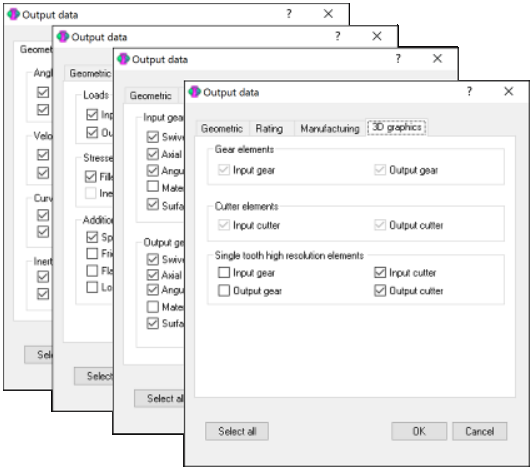
Output data Output data is grouped into geometric, rating, and manufacturing data. Check boxes determine whether or not to calculate the specified terms.
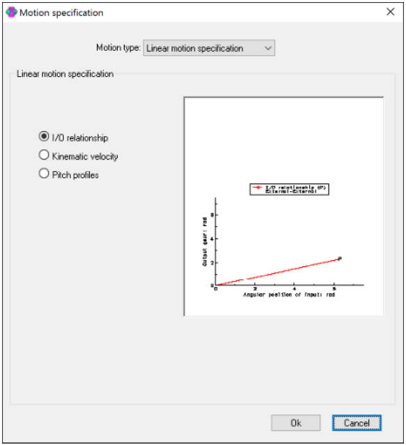
Motion specification Motion is specified in the “Motion specification” application dialog. Default settings are for linear motion (circular gears). The “combobox” control at the top of the dialog allows selection of various non-linear motion types. A message is displayed when the number of teeth on the input gear and output gear are different (i.e., net gear ratio not 1:1). Additionally, another message is displayed when the shaft angle is not zero (i.e., ≠0).
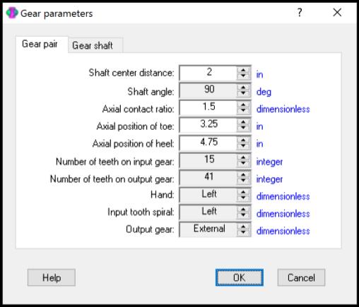
Gear parameters This module is used to specify the nominal gear pair data. Automatically displayed are the dimensions that correspond to the units specified in the units module. Pre-set values are selected using the “spin-buttons” to the immediate right of the displayed results. These spin-buttons “read only” and the user cannot arbitrarily specify values. The white background spin buttons accept user input. A message box is displayed when the user attempts to specify invalid data. Further, a subtle aspect of hypoid, spiral bevel, and worm gearing is the “hand”.
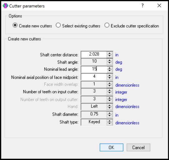
Cutter parameters This module is used to specify the nominal cutter pair data. The designer has the option to create new cutters or select existing cutters for the integrated design and manufacturing process. Automatically displayed are the dimensions that correspond to the units specified in the units module. Pre-set values are selected using the “spin-buttons” to the immediate right of the displayed results.
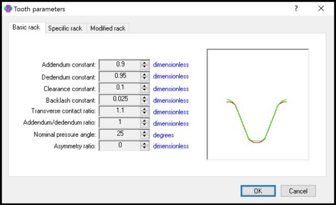
Tooth specifications This module is used to specify the nominal gear tooth data. Automatically displayed are the dimensions that correspond to the units specified in the units module. Pre-set values are selected using the “spin-buttons” to the immediate right of the displayed results. The tooth profile can be specified in terms of a basic rack or for a standard involute tooth profile.
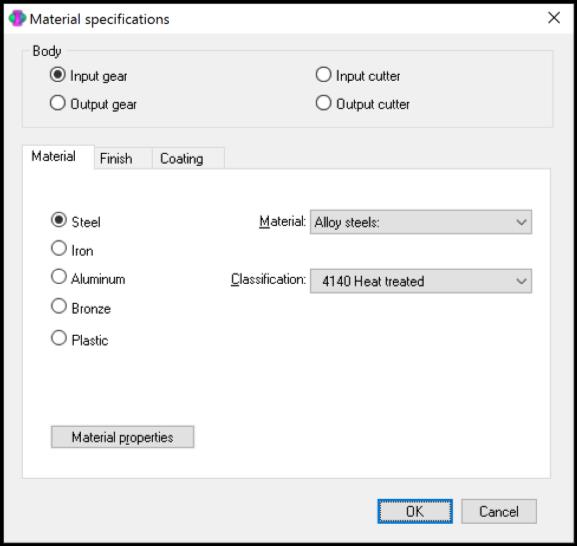
Material specifications This module is used to specify the material for both the cutter and gear elements. Material choices include are based on the MS Excel spreadsheet.
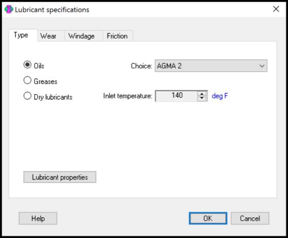
Lubricant specifications An expression for the coefficient of friction for full film EHD lubrication is presented (i.e., when the two gear teeth are entirely separated by the lubricant) for predicting the efficiency of gear pairs with relative sliding at the mesh. Inherent is the assumption of fully flooded contact (versus starved). Increased contact life occurs when specific lubricant film thickness is greater than 3. Surface roughness decreases with each mesh cycle reaching a plateau or fixed value. This phenomenon is oftentimes referred to as seating or “running-in” and increases the specific film thickness. The minimum film thickness is predicted using the classical expression developed by Hamrock and Dowson.
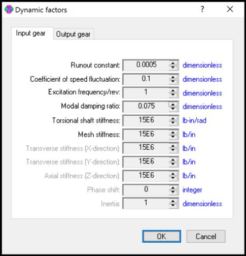
Dynamic factors This module is used to specify data that affect the normal tooth load. An elementary 1-dof dynamic model based on nominal contact conditions is introduced. This model does not take into account the dynamic response of the gearbox.
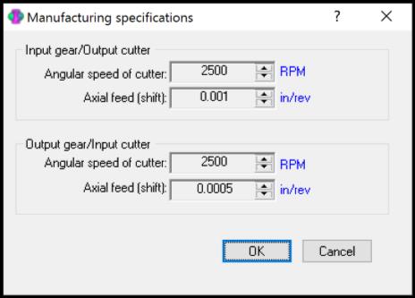
Manufacturing specifications The fabrication of the gears is affected by both the speed and feed of the cutter. The speed and feed for the input gear and output gear are specified in the dialog “Manufacturing specifications. . . ” in the menu item “Settings”.
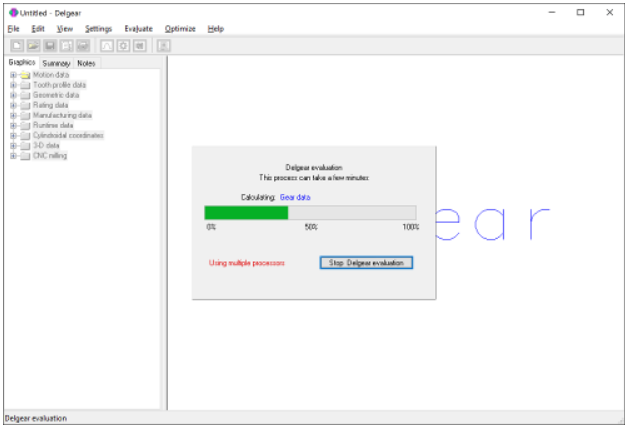
Status Indicator Included with each evaluation of a gear data set is a status bar is to indicate percent of calculations performed. The CPU runtime typically varies from 30 seconds to 3 minutes depending on gear resolution and hardware. Additional time is necessary for FEA of fillet stress (approximately 10 minutes). Another feature of Delgear is multi-processing where the software uses multiple processors at certain stages. When this occurs, a message at the bottom left appears. Delgear evaluation process can be terminated by clicking on the “Stop Delgear evaluation” push button control. This cancelation of the calculation process reverts data back to the original data prior to initiating the evaluation. This termination may not be immediate as the software checks after each calculation prior to proceeding.
Home | About | Examples | Add-ons | Licenses | Prototype | Contact
|